4.3 Collector
This page explains the collector components.
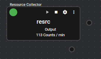
4.3.1 Resource Collector#
This component collects system resources of Operating machine.
It collects and registers CPU utilization, memory consumption, and other resource utilization information of the device on which this application is running.
4.3.1.1 Basic Information#
The basic information of the Resource Collector is as follows:
| Item | Description |
|---|---|
| Base name | Resource Collector |
| Description | Collects system resources of Operating machine. |
| Consumption points | 0 |
| Port | Input: 0 Output: 1 Outputs the collected system resources of Operating machine. For details on output data, see Output Data Items. System: 1 Outputs the component’s operating status and error information. For details on the output error information, see List of Error Codes. |
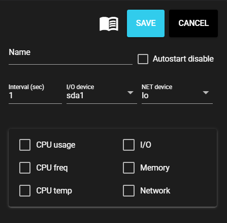
4.3.1.2 Settings#
The Resource Collector settings are as follows:
| Item | Description |
|---|---|
| Name | Enter a name for the component. Note: Must be different from any other component name. |
| Autostart disable | Set to ON to disable the component’s Autostart. |
| Interval (sec) | Enter the interval at which the collector gets data. |
| I/O device | Select the I/O device from which data is collected. |
| NET device | Select the network device from which data is collected. |
| CPU usage | Set to ON to enable the collection of Operating machine’s CPU utilization information. |
| CPU clock rate | Set to ON to enable the collection of Operating machine’s CPU clock rate information. Note: Not available on Windows Note: Also may not be available on Linux |
| CPU temp | Set to ON to collect CPU temperature information. Note: Not available on Windows Note: Also may not be available on Linux |
| I/O | Set to ON to collect the I/O status information for the device selected in [I/O device]. Note: If I/O status collection is enabled in the Windows version, the processing may not be able to keep up with the acquisition interval of 1 second. (If delay occurs, make an adjustment by setting the interval to 5 seconds or more.) |
| Memory | Set to ON to enable the collection of Operating machine’s used memory information. |
| Network | Set to ON to collect the network status information for the device selected in [NET device]. |
4.3.1.3 Output Data Items#
The Resource Collector outputs the following data:
| Item | Column name | Data type | Description |
|---|---|---|---|
| CPU usage | cpu_usage | double | Collects the CPU utilization information. Unit is % with a range from 0.000 to 100.000. |
| Utilization rate per CPU core | cpu_core_usage | double[n] | Collects the utilization information of each CPU core. Unit is % with a range from 0.000 to 100.000. |
| CPU execution frequency | cpu_core_freq | int32[n] | Collects the execution frequency information of each CPU core. Unit is kHz. |
| CPU temp | cpu_temp | double | Collects the CPU temperature information. Unit is ℃. |
| I/O information collection device name | I_O | string | Name of device whose I/O information is being collected (physical only) |
| Average number of read requests processed | kb_r_s | double | Collects the average number of read requests processed. Unit is KB. |
| Average number of write requests processed | kb_w_s | double | Collects the average number of write requests processed. Unit is KB. |
| Average read/write count | IOPS | double | Collects the average read/write count. Unit is KB. |
| Free disk space (MB) | storage_free_space_mb | double | Collects information on free space on the specified disk. Unit is MB. |
| Disk usage (%) | storage_usage | double | Collects information on rate of usage of the specified disk. Unit is % with a range from 0.0 to 100.0. |
| Total memory | mem_total | int32 | Collects total memory space information. Unit is KB. |
| Memory used | mem_used | int32 | Collects information on memory space used. Unit is KB. |
| Memory usage rate | mem_usage | double | Collects information on rate of memory used. Unit is % with a range from 0.0 to 100.0. |
| Total SWAP space | swap_total | int32 | Collects total SWAP space information. Unit is KB. |
| SWAP space used | swap_used | int32 | Collects information on SWAP space used. Unit is KB. |
| SWAP usage rate | swap_usage | double | Collects information on rate of SWAP space used. Unit is % with a range from 0.0 to 100.0. |
| Total bytes received | rx_bytes1 | uint64 | Collects the number of bytes received. Unit is byte. |
| Total packets received | rx_pckt1 | uint64 | Collects the number of packets received. |
| Total bytes sent | tx_bytes1 | uint64 | Collects the number of bytes sent. Unit is byte. |
| Total packets sent | tx_pckt1 | uint64 | Collects the number of packets sent. |
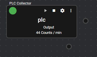
4.3.2 PLC Collector#
This component collects data from PLC register/variable information.
It is connected to PLCs of various manufacturers such as Omron and Mitsubishi to collect and register data from register/variable information.
For some PLCs, you can set register information by importing the file output using the ladder editing tool.
4.3.2.1 Basic Information#
The basic information of the PLC Collector is as follows:
| Item | Description |
|---|---|
| Base name | PLC Collector |
| Description | Collects data from PLC register/variable information. |
| Consumption points | 0 |
| Port | Input: 0 Output: 1 Outputs data collected from the PLC according to Settings. System: 1 Outputs the component’s operating status and error information. For details on the output error information, see List of Error Codes. |
| Other | - You can test connection with a PLC. For more information, see Test Connection. - Addresses can be set automatically. For more information, see Auto address setting. |
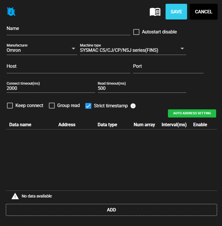
4.3.2.2 Settings#
The PLC Collector settings are as follows:
| Item | Description |
|---|---|
| Name | Enter a name for the component. Note: Must be different from any other component name. |
| Autostart disable | Set to ON to disable the component’s Autostart. |
| Manufacturer | Select the manufacturer of the connecting PLC. Note: You can select from the following manufacturers: - Mitsubishi - Jtekt - Omron - Keyence - Panasonic |
| Machine type | Select the machine type of the connecting PLC. Note: Machine types that can be selected depend on the manufacturer. |
| Host | Enter the host name or IP address of the connecting PLC. |
| Port | Enter the port for connecting PLC |
| Connect timeout(ms) | Enter the timeout duration for connecting. |
| Read timeout(ms) | Enter the timeout duration for reading. |
| Keep connect | Set to ON if PLC connection is not disconnected each time a query is made. |
| Group read | Set to ON to read multiple word registers at one time. |
| Block read | Set to ON to read multiple bit registers and word registers at one time. |
| Strict timestamp | Set to ON to set a strict timestamp based on collected data. |
- The PLC Collector output data is defined by the following settings:
| Item | Description |
|---|---|
| Data Name | Enter name of data. |
| Address | Enter the PLC register address. |
| Program | Select the register program number. Note: Available only when the manufacturer is Jtekt. |
| Data type | Select the data type of the register value to be acquired. |
| Num array | Enter the range from which value is retrieved from among the consecutive registers starting from the input address. |
| Interval(ms) | Enter the interval for retrieving register values. |
| Enable | Set to ON to retrieve register values. |
4.3.2.3 Settings (Serial Connection)#
The PLC Collector (Serial Connection) settings are as follows:
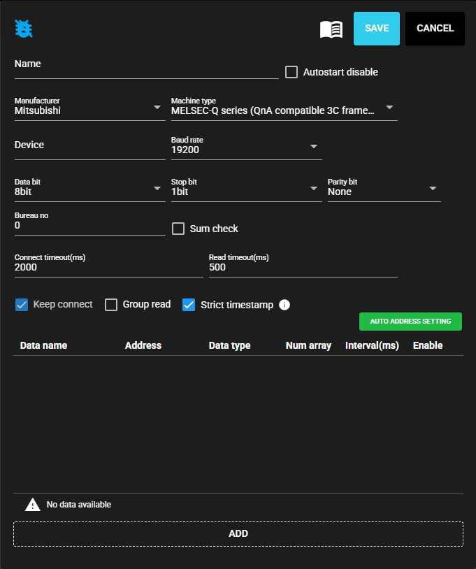
| Item | Description |
|---|---|
| Device | Enter the serial communication device to use. |
| Baud rate | Select the baud rate for serial communication. |
| Data bit | Select the data bit for serial communication. |
| Stop bit | Select the stop bit for serial communication. |
| Parity bit | Select the parity bit for serial communication. |
| Bureau no | Enter the bureau number for Mitsubishi 3C frame. |
| Sum check | Set to ON to perform checksum for Mitsubishi 3C frame. |
- The PLC Collector output data is defined by the following settings:
| Item | Description |
|---|---|
| Data Name | Enter name of data. |
| Address | Enter the PLC register address. |
| Program | Select the register program number. Note: Available only when the manufacturer is Jtekt. |
| Data type | Select the data type of the register value to be acquired. |
| Num array | Enter the range from which value is retrieved from among the consecutive registers starting from the input address. |
| Interval(ms) | Enter the interval for retrieving register values. |
| Enable | Set to ON to retrieve register values. |
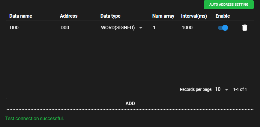
4.3.2.4 Test Connection#
You can test connection with the specified destination by following the steps below:
-
Open the settings screen for the registered PLC Collector.
-
Press [Test].

-
Test connection is attempted with the specified destination, and the result is displayed at the bottom of the settings screen.
4.3.2.5 Auto address setting#
With some PLCs, you can set addresses automatically at once by reading the file output by the ladder editing tool.
-
In the ladder editing tool, output the created ladder as a file. The output file format differs depending on the PLC manufacturer and machine type. Sample files are provided below:
-
Mitsubishi MELSEC-Q series (QnA compatible 3E frame), MELSEC-iQ-R series (QnA compatible 3E frame)
-
Omron SYSMAC CS/CJ/CP/NSJ series (FINS)
-
Keyence KV-8000 series (Upper Link)
-
-
Press [Auto address setting].
-
Select the file that you output with the ladder editing tool.
-
The address is automatically set based on the file.
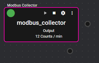
4.3.3 Modbus Collector#
This component collects data from Modbus compatible devices.
This component is the Modbus master and collects and registers data from Modbus slave devices.
4.3.3.1 Basic Information#
The basic information of the Modbus Collector is as follows:
| Item | Description |
|---|---|
| Base name | Modbus Collector |
| Description | Collects data from Modbus compatible devices. |
| Consumption points | 2 |
| Port | Input: 0 Output: 1 Outputs data collected from Modbus compatible devices according to Settings. System: 1 Outputs the component’s operating status and error information. For details on the output error information, see List of Error Codes. |
| Other | You can test connection with Modbus compatible devices. For more information, see Test Connection. |
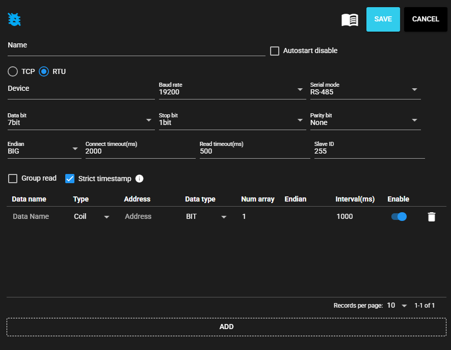
4.3.3.2 Settings#
The Modbus Collector settings are as follows:
-
When TCP is selected as the communication method

-
When RTU is selected as the communication method
| Item | Description |
|---|---|
| Name | Enter a name for the component. Note: Must be different from any other component name. |
| Autostart disable | Set to ON to disable the component’s Autostart. |
| Communication method | Select TCP or RTU |
| Host | Enter the host name or IP address of the connecting Modbus device. Note: Only available when the communication method is TCP. |
| Port | Enter the port for connecting to the PLC. Note: Only available when the communication method is TCP. |
| Device | Enter the serial communication device to use. Note: Only available when the communication method is RTU. |
| Baud rate | Select the baud rate for serial communication. Note: Only available when the communication method is RTU. |
| Serial mode | Select the serial communication mode. Note: Only available when the communication method is RTU. |
| Data bit | Select the data bit for serial communication. Note: Only available when the communication method is RTU. |
| Stop bit | Select the stop bit for serial communication. Note: Only available when the communication method is RTU. |
| Parity bit | Select the parity bit for serial communication. Note: Only available when the communication method is RTU. |
| Endian | Select a byte order. |
| Connect timeout(ms) | Enter the timeout duration for connecting. |
| Read timeout(ms) | Enter the timeout duration for reading. |
| Slave ID | Enter the Slave ID of the connecting device. |
| Group read | Set to ON to read multiple word registers at one time. |
| Strict timestamp | Set to ON to set a strict timestamp based on collected data. |
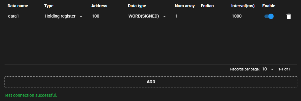
- The Modbus Collector output data is defined by the following settings:
| Item | Description |
|---|---|
| Data Name | Enter name of data. |
| Type | Select the type of register value. |
| Address | Enter the register address. Note: According to Modbus specifications, the address range is usually set to "1 to 65536," but when setting in SpeeDBee Synapse, it is necessary to set an address range shorter by 1, specifically, as "0 to 65535." |
| Data type | Select the data type of the register value to be acquired. |
| Num array | Enter the range from which value is retrieved from among the consecutive registers starting from the input address. |
| Endian | Select the byte order in register units. |
| Interval(ms) | Enter the interval for retrieving register values. |
| Enable | Set to ON to retrieve register values. |
4.3.3.3 Test Connection#
You can test connection with the specified destination by following the steps below:
-
Open the settings screen for the registered Modbus Collector.
-
Press [Test].
-
Test connection is attempted with the specified destination, and the result is displayed at the bottom of the settings screen.
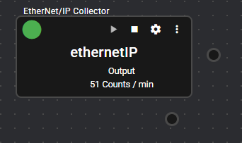
4.3.4 EtherNet/IP Collector#
This component collects data from EtherNet/IP-enabled devices.
This component acts as an originator and collects and registers data from Ethernet/IP-enabled devices.
4.3.4.1 Basic Information#
The basic information of the EtherNet/IP Collector is as follows:
| Item | Description |
|---|---|
| Base name | EtherNet/IP Collector |
| Description | Collects data from EtherNet/IP-enabled devices. |
| Consumption points | 2 |
| Port | Input: 0 Output: 1 Outputs data collected from EtherNet/IP-enabled devices according to Settings. System: 1 Outputs the component’s operating status and error information. For details on the output error information, see List of Error Codes. |
| Other | Variables can be set automatically. For more information, see Auto variable setting. |
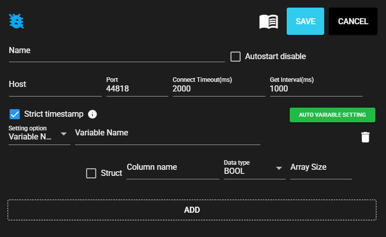
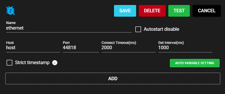
4.3.4.2 Settings#
The EtherNet/IP Collector settings are as follows:
| Item | Description |
|---|---|
| Name | Enter a name for the component. Note: Must be different from any other component name. |
| Autostart disable | Set to ON to disable the component’s Autostart. |
| Host | Enter the host name or IP address of the EtherNet/IP-enabled device. |
| Port | Enter the port for the EtherNet/IP-enabled device. |
| Connect timeout(ms) | Enter the timeout duration for connecting. |
| Get Interval(ms) | Enter the interval for retrieving data. |
| Strict timestamp | Set to ON to set a strict timestamp based on collected data. |
- The EtherNet/IP Collector output data is defined by the following settings:
| Item | Description |
|---|---|
| Setting Option | Select the setting option for the data to be acquired. |
| Variable Name | Enter a tag name. Note: This item can be entered only when the Setting Option is Variable Name. |
| Struct | Set to ON to register multiple members. Note: This item can be set only when the Setting Option is Variable Name. |
| Class ID | Enter the Class ID of CIP object. Note: This can be entered only when the Setting Option is CIPObject. |
| Instance ID | Enter the Instance ID of CIP object. Note: This can be entered only when the Setting Option is CIPObject. |
| Attribute ID | Enter the attribute ID of CIP object. Note: This can be entered only when the Setting Option is CIPObject. |
| Column name | Name of member |
| Data type | Data type of member |
| Array size | Array size of member |
4.3.4.3 Test Connection#
You can test connection with the specified destination by following the steps below:
-
Open the settings screen for the registered EtherNet/IP Collector.
-
Press [Test].
-
Test connection is attempted with the specified destination, and the result is displayed at the bottom of the settings screen.
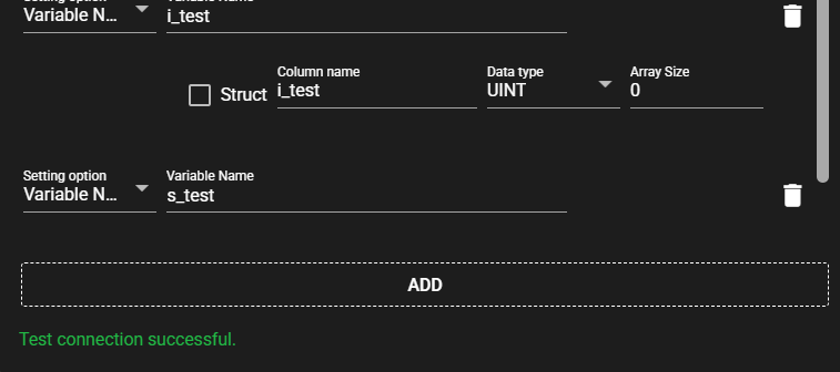
4.3.4.4 Auto variable setting#
Variables can be automatically set by converting the global variable information exported by Sysmac Studio to a text file into a specified format and reading it.
-
Convert the global variable information exported by Sysmac Studio to a text file with the following column information:
- HOST
- NAME
- DATATYPE
- ADDRESS
- COMMENT
- TAGLINK
- RW
- POU
ExampleHOST NAME DATATYPE ADDRESS COMMENT TAGLINK RW POU b_test BOOL test1 TRUE RW i_test UINT test2 TRUE RW s_test STRING(256) test3 TRUE RW -
Press [Auto variable setting].
-
Select the prepared text file.
-
The variable is automatically set based on the file.
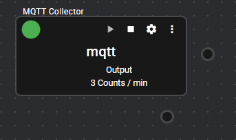
4.3.5 MQTT Collector#
This component collects JSON data using the MQTT protocol.
This component subscribes to a specific topic name in MQTT. It parses the received data as JSON data and registers the content as collected data.
The format of JSON data that can be received is the same as that of JSON serializer output.
In addition to connecting with the regular MQTT broker, it can also connect with AWS IoT Core.
4.3.5.1 Basic Information#
The basic information of the MQTT Collector is as follows:
| Item | Description |
|---|---|
| Base name | MQTT Collector |
| Description | Data collection is performed using the MQTT protocol (Subscribe). |
| Consumption points | 2 |
| Port | Input: 0 Output: 1 Outputs the data received from the MQTT broker specified in Settings. System: 1 Outputs the component’s operating status and error information. For details on the output error information, see List of Error Codes. |
| Other | You can test connection with the MQTT broker. For more information, see Test Connection. |
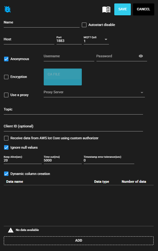
4.3.5.2 Settings#
The MQTT Collector settings are as follows:
| Item | Description |
|---|---|
| Name | Enter a name for the component. Note: Must be different from any other component name. |
| Autostart disable | Set to ON to disable the component’s Autostart. |
| Host | Enter the host name or IP address of the MQTT broker. |
| Port | Enter the port for the MQTT broker. |
| MQTT Qos | Select the Quality of Service for MQTT. |
| Anonymous | Set to ON to disable user authentication. |
| User name | Enter the authenticated user name. Note: Can be entered only when Anonymous is disabled. |
| Password | Enter the authenticated password. Note: Can be entered only when Anonymous is disabled. |
| Encryption | Set to ON to enable encryption. |
| CA Certificate | Upload the CA Certificate to be used for encrypt communication. Note: You can only upload it when encryption is enabled. |
| Use a proxy | Set to ON to communicate with the MQTT broker via a proxy server. |
| Proxy server | Select a proxy server. Note: You must configure the server to be used in advance on the Proxy Settings screen. |
| Topic | Enter the topic for collection. |
| Client ID | MQTT Client ID Note: You may need to specify this item depending on the specifications of the connecting device. If omitted, a random string will be used. Note: If multiple components are connecting to the same MQTT broker, make sure that there is no duplication in the client IDs. Otherwise, communication will not be performed correctly. |
| Receive data from AWS Iot Core using custom authorizer | Set to ON if you want to use the AWS IoT Core custom authentication feature to receive data from AWS IoT Core. Note: You must have enabled custom authentication settings in AWS Iot Core. For more information, see here. |
| Ignore null values | This affects the behavior when the value in the received data is null. When this option is selected, NULL is ignored and no error occurs. When this option is not selected, error occurs when a NULL value is received. |
| Keep Alive(sec) | Enter MQTT keepalive interval. |
| Time out(ms) | Enter timeout seconds for MQTT broker connection. |
| Timestamp error tolerance(sec) | Enter timestamp error tolerance. |
| Dynamic column creation | Set to ON to dynamically create columns from data received from the MQTT broker. Note: 1 Columns are generated only after data is received from the MQTT broker. Note: 2 Dynamically generated columns disappear when the component stops. If you want to use the data, register it as a fixed column. |
| Data Name | Enter the name of fixed column. |
| Data type | Select the data type of fixed column. |
| Number of data | Enter the array size of the fixed column. |
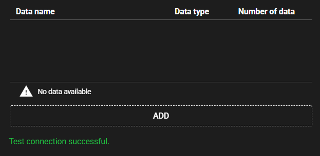
4.3.5.3 Test Connection#
You can test connection with the specified destination by following the steps below:
-
Open the settings screen for the registered MQTT Collector.
-
Press [Test].
-
Test connection is attempted with the specified destination, and the result is displayed at the bottom of the settings screen.
Precautions for MQTT Collector Test Connection
Test connection is only available in the following cases:
- Component has stopped.
- Component status is Error.
4.3.5.4 Format of received data#
The format of the data received by MQTT Collector is compatible with the JSON serializer. Check the output data items of the JSON serializer.
Example of Data Transmission Using mosquitto
To receive data with the MQTT Collector, the key must be specified as "records" because the JSON "records" contains the data.
For example, to publish data to a topic using mosquitto_pub, the following command is necessary:
$ mosquitto_pub -d -h 192.168.1.10 -p 1883 -t "topic" -m '{"records": [{"data1":1, "data2":"Hello,World"}, {"data3":[111,222,333], "data4":3.14}]}'
4.3.5.5 Receiving Data from Cloud Service#
The MQTT Collector can receive data from the following cloud services. See the following notes for each:
AWS IoT Core
In order for the MQTT Collector to receive data sent to AWS IoT Core,
you must use the “Receive data from AWS IoT Core using custom authorizer” option.
You also need to set it up on the cloud side.
For more information, see Custom Authentication and Authorization on the official AWS page.
This information is current as of June 2024.
Azure IoT Hub
To receive data from Azure IoT Hub, you need a setup to meet the IoT Hub specifications. The MQTT Collector can receive data sent as “cloud-to-device.”
The MQTT Collector cannot receive data sent to IoT Hub from other devices.
Data cannot be broadcast to multiple devices in a cloud-to-device setup.
This information is current as of June 2024. For more information, please check the official pages below:
- Communicating with IoT Hub using MQTT protocol
- Sending cloud-to-device messages from IoT Hub
- Sending messages to devices from the cloud using IoT Hub (Python)
- Controlling access to IoT Hub using Shared Access Signature (SAS token)
- Your IoT Hub must be Standard tier. The IoT Hub cannot be used with Basic or Free tier.
- Host: {IoT Hub name}.azure-devices.net
- Port: 8883
- User name: {IoT Hub name}.azure-devices.net/{Device Id}/?api-version=2021-04-12
- Password: SAS token
- Topic: devices/{Device Id}/messages/events/"
- Client ID: {Device Id}
- Encryption: Enabled
- CA Certificate: DigiCert root certificate (DigiCert Global Root G2)
The MQTT broker in Azure Event Grid is not currently supported.
4.3.5.6 Receiving Data from Various Emitters#
Data generated by a JSON serializer can be sent to various emitters and received by other MQTT Collectors.
| Sender | Receiver | Yes/No |
|---|---|---|
| MQTT Emitter | MQTT Collector | 〇 Note: Connection with the same MQTT broker must be set up. |
| Cloud Emitter for AWS | MQTT Collector | 〇 Note: The MQTT Collector must have a custom authentication setup. |
| Cloud Emitter for Azure | MQTT Collector | × Note: Data for devices cannot be received by the MQTT Collector. |
Precautions for Receiving Data from Other Emitters
When receiving data from various emitters, note the following:
1. When sending data by the emitter one set at a time:
Example:
Switch the data of the sending JSON serializer at one set.
Set the receiving MQTT Collector error tolerance (in seconds) to 10.
In this case, if the data can be received within 10 seconds from data registration, the data is registered with the original timestamp. However, keep in mind that data is sent to the cloud frequently.
2. When sending aggregated values by the emitter:
Example:
Switch the data of the sending JSON serializer at one set.
The sending JSON serializer takes the average of data aggregated at the input port, with a window width of 60 seconds.
Set the receiving MQTT Collector error tolerance (in seconds) to 10.
In this case, the average of the values is registered and sent at the emitter, with the specified width. The Collector receives this and registers the data with the original timestamp. The load on the network is small because not all data is sent.
3. When the sender stores data for a specified time and sends it by the emitter:
Example:
Switch the data of the sending JSON serializer in 60 seconds.
Set the receiving MQTT Collector error tolerance (in seconds) to 0.
In this case, the data is registered with the current time at which the entire data was received. Note that data is not registered with the original timestamp.
4. When the sender collects data for a specified time and sends it by the emitter (with the timestamp registered without change):
To achieve this, you need at least the following setup:
Example:
Switch the data of the sending JSON serializer in 10 to 30 seconds.
Set the receiving MQTT Collector error tolerance (in seconds) to 60.
Set the delay time to 61000 (milliseconds) on the input port of the component connected to the MQTT Collector.
This setting allows data to be registered if the data timestamp sent falls within 60 seconds. However, check the transmission and reception and make sure that there is no problem with the performance, sufficiently verifying that the received data is being processed as expected.
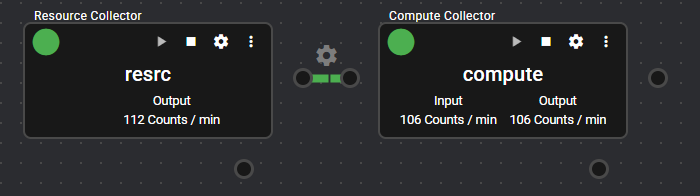
4.3.6 Compute Collector#
This component performs calculations with any expression.
It receives data output by another component from the input port, and outputs as new data the result of calculating the data by applying any calculation formula.
You can use arithmetic and logical operations, as well as a variety of other functions, in the calculation formula.
4.3.6.1 Basic Information#
The basic information of the Compute Collector is as follows:
| Item | Description |
|---|---|
| Base name | Compute Collector |
| Description | Receives data from other collectors, performs calculations, and treats it as new data. |
| Consumption points | 2 |
| Port | Input: 1 Receives data from other components. Output: 1 Outputs the calcuation result according to the Settings. System: 1 Outputs the component’s operating status and error information. For details on the output error information, see List of Error Codes. |
| Other | This component can open the input port settings window and set up aggregation of data received from other components. For more information, see Import setting. |
4.3.6.2 Settings#
The Compute Collector settings are as follows:

| Item | Description |
|---|---|
| Name | Enter a name for the component. Note: Must be different from any other component name. |
| Autostart disable | Set to ON to disable the component’s Autostart. |
| Variable Name | Name automatically assigned to the input data |
| Component Name | Select a component from the input port data list. |
| Data Name | Select data from the data list for the component selected above. |
| Aggregation | Select aggregate value. Note: Available only if you have applied the aggregation option to the component’s data. For more information on aggregation, see IN Port. |
- The Compute Collector output data is defined by the following settings:
| Item | Description |
|---|---|
| Data Name | Enter name of data. |
| Data type | Select a data type. |
| Trigger variable | Variable that triggers the execution of calculation The variable set in the input data can be selected. Calculation is executed once the selected variable is updated. |
| Expression | Enter the expression to be executed by the Collector. Note: Click the icon to the right of “Expression” in the title to display an example and a list of elements that can be used in the expression. |
4.3.6.3 Import setting#
For added Compute Collectors, you can open the Compute Collector input port settings window by pressing "Import setting" on the setting screen. In the input port settings window, you can set up aggregation of data received from other components. For more information, see IN Port.