10.6 Tutorial
This section provides a simple tutorial on how to use i-Trigger.
10.6.1 Assumed Use Cases#
In this tutorial, error detection will be performed according to the following use cases.
When an error is detected in the data collected from the PLC, confirm the video and collected data before and after the error in the Video Viewer. (Note: This is an example of using custom components to simulate a PLC Collector.)

-
Collect the following data from the PLC:
- Error detection flag
- Pressure
-
Record video with a single network camera.
- When the error detection flag is turned ON, event recording starts.
- Record 5 seconds before the error detection flag is detected and 5 seconds after the error detection flag is turned OFF.
- The data displayed in the Video Viewer includes the error detection flag obtained from the PLC, the pressure, and the video taken in that section.
10.6.2 Custom Component Configuration (Simulated PLC Collector)#
First, configure a custom component to collect error detection and pressure data.
10.6.2.1 Custom Component Code#
Copy the following code, paste it into a text editor such as Notepad, and save it on your PC as a file named dummy_plc.py. Specify UTF-8 as the character encoding.
from speedbeesynapse.component.base import HiveComponentBase, HiveComponentInfo, DataType
import time
import json


@HiveComponentInfo(uuid='12318c73-fe45-fded-150a-b95c894f3692', name='PLC Collector(Dummy)', inports=0, outports=1)
class HiveComponent(HiveComponentBase):
    def __init__(self):
        # called at creating component instance
        pass
    def __del__(self):
        # called at deleting component instance
        pass

    def premain(self, param):
        # called before main()
        # create a column to register dummy data
        self.data = self.out_port1.Column('Pressure', DataType.INT16)
        self.flag = self.out_port1.Column('anomaly_detection_flag', DataType.BOOLEAN)

    def postmain(self, param):
        # called after main() finished
        pass

    def main(self, param):
        value = False
        count = 0
        while self.is_runnable():
            ts = self.get_timestamp()
            pressure = 50
            count += 1
            # register error data every 30 counts
            if (count % 30) == 0:
                value = True
                pressure = 100
            else:
                value = False
            # register dummy data
            self.flag.insert(value, ts)
            self.data.insert(pressure, ts)

            time.sleep(1.0)

    def notify_stop(self):
        # called before the component received stop request from system
        pass
The above code executes the following process:
- At approximately 30-second intervals, set the error detection flag to True and register data.
- Register pressure at 50 when normal.
- When an error occurs, register the pressure value at 100.
10.6.2.2 Register Custom Components#
Configure the saved Python source code for use in SpeeDBee Synapse.
-
Click on Custom Components in the Server Settings Icon.

-
Click on Add for Custom Components.

-
Select the dummy_plc.py you just saved.

-
Verify that the custom component is displayed on the screen.
When dummy_plc.py is displayed, click Close on the dialog.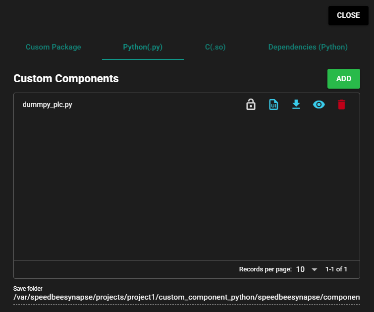
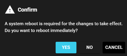
-
When prompted to restart, click Yes.
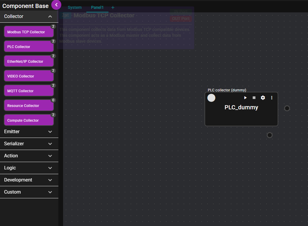
-
Drag and drop PLC Collector (Dummy) from Custom on the left side of the Flow Editor to the center of the editor.

-
Set the name to PLC_dummy and click Save.
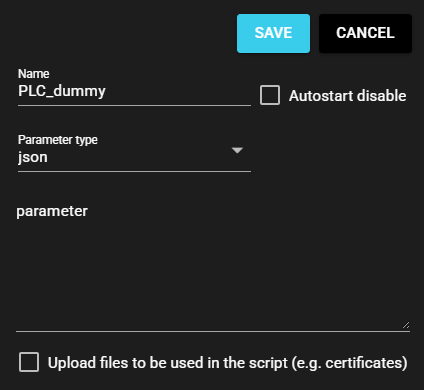
-
The custom component is ready.

10.6.3 Component Placement and Configuration#
Here you can configure various components for using i-Trigger.
10.6.3.1 VIDEO Collector Configuration#
Configure the VIDEO Collector to record video.
If there are no network cameras available, you may skip this configuration step.
-
Drag and drop VIDEO Collector from Collector on the left side of the Flow Editor to the center of the editor.
-
Set the name to Camera1 and input the specified URL of the camera in the RTSP URL field. Then click Save.

-
The VIDEO Collector Camera1 is ready.

10.6.3.2 Event Trigger Configuration#
Event triggers allow you to set conditions for error detection.
-
Start PLC_dummy and Camera1 before configuring the event trigger. Click Start in the upper right of the panel.

-
Drag and drop Event Trigger from Logic on the left side of the Flow Editor to the center of the editor.

-
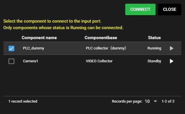
For the component to be connected to the IN Port, place a check mark in PLC_dummy and click Connect.
-
Set the name to anomaly_detection. Input other items by referring to the following and click Save.
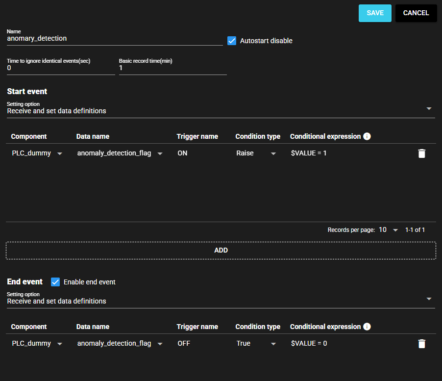
Item Value Supplementary Information Time to ignore identical events(sec) 0 Set to 0 since it is ignored this time and no setting is required. Basic record time(min) 1 Start event - - Component PLC_dummy Data name Error detection flag Trigger name ON Condition type Raise Conditional expression $VALUE = 1 Raise condition for flag to be True. End event - - Component PLC_dummy Data name Error detection flag Trigger name OFF Condition type Raise Conditional expression $VALUE = 0 Falling condition for flag to be False. -
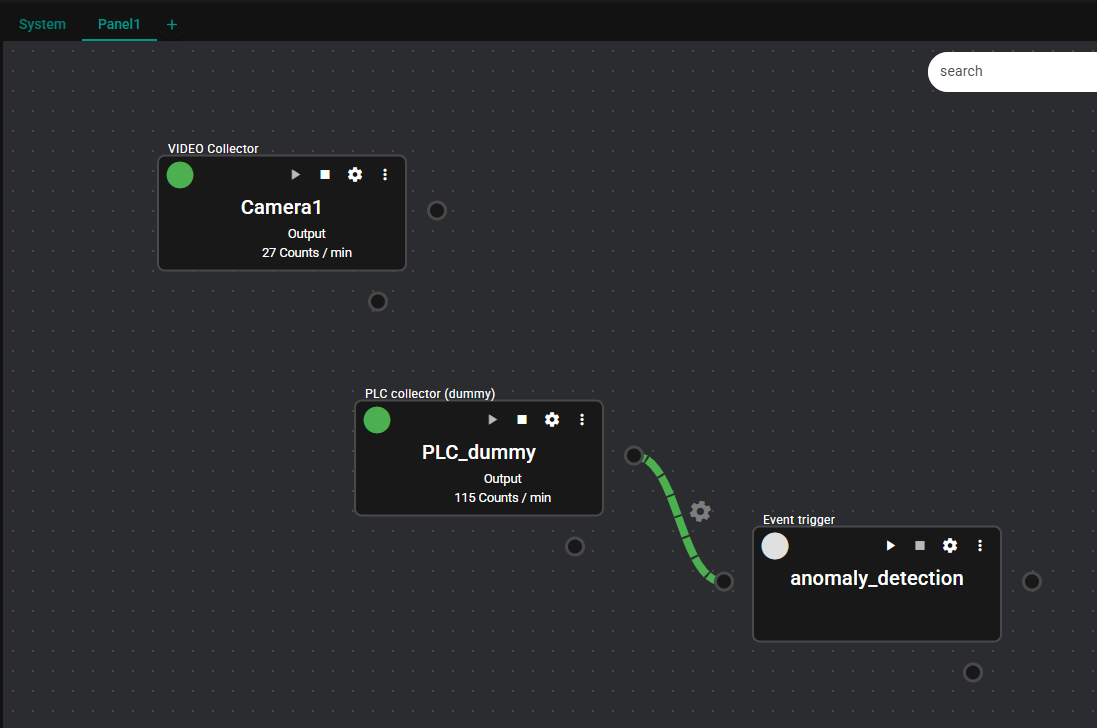
The event trigger anomaly_detection configuration is complete.
10.6.3.3 Event Recorder Configuration#
Finally, configure the Event Recorder settings. You can also configure here the settings of the record interval in the event of an error.
-
Start the event trigger anomaly_detection. Click Start Icon.
-
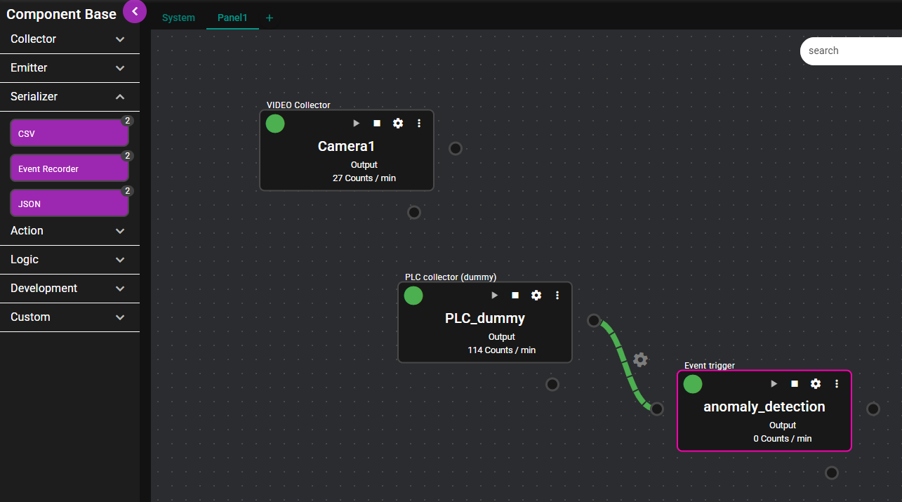
Drag and drop Event Recorder from Serializer on the left side of the Flow Editor to the center of the editor.
-
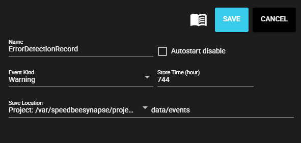
Set the name to anomaly_detection_rec. Select Warning for Event Kind. Then click Save.
-
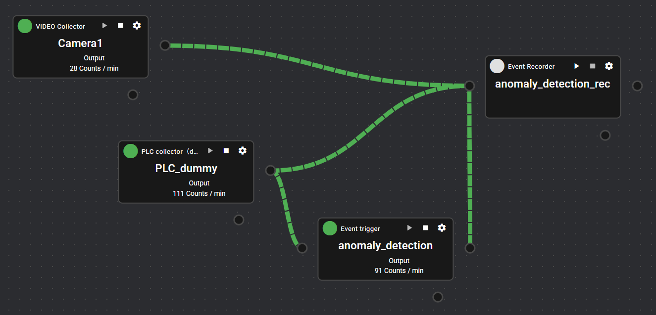
Connect the flowlinks of PLC_dummy, Camera1, and anomaly_detection to the anomaly_detection_rec.
-
Open the IN Port settings for anomaly_detection_rec.
-
Configure the IN Port settings and click Save. Please refer to the following to configure the input value settings.
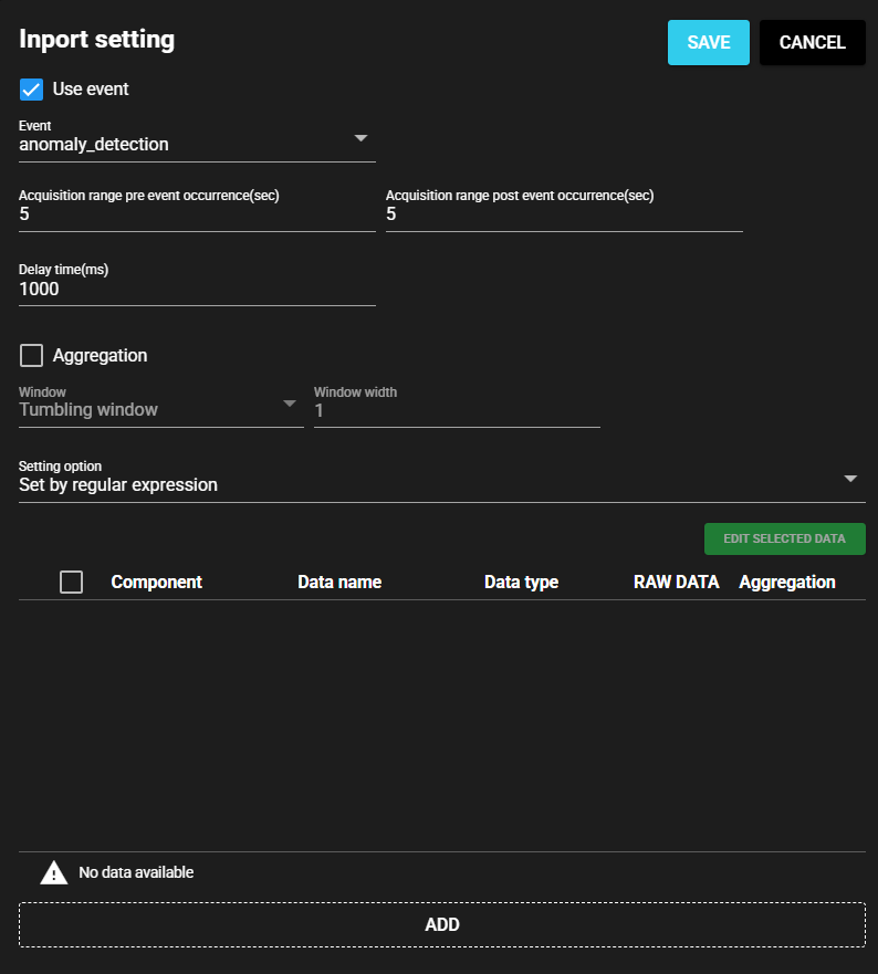
Item Value Supplementary Information Use event Check ON If you do not configure this setting, the range of the event occurrence will not be recorded in the Event Recorder. Event anomaly_detection If you do not configure this setting, the range of the event occurrence will not be recorded in the Event Recorder. Acquisition time pre event occurrence(sec) 5 Acquisition time post event occurrence(sec) 5 -
This completes the configuration of all event record settings.
10.6.4 Confirmation of Operation#
Operate the data flow for which you have configured settings so far.
-
Start the configured component.
-
Verify that the placed component starts normally. If there are errors in the component lamps, check and, if necessary, revise the settings.
-
After running for more than a few minutes, check the Video Viewer. Click Video Viewer Icon.

-
Click on Event Record in the left part of the Video Viewer. Verify that the anomaly_detection_rec appears in the list.

-
Click on any anomaly_detection_rec and verify that the General Video Viewer is displayed.

-
Click on the Play Icon to play back the event record. If the pressure is confirmed to be 100 at the timing when the error detection is set to 1 simultaneously with the event recording for approximately 10 to 11 seconds, the system is working normally.

-
This concludes the Tutorial.