4.9 Action
This page explains the action components.
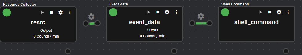
4.9.1 Shell Command#
This component executes any shell command by using collected data.
When the component receives data from the input port, it executes the shell command specified by a parameter.
For the string specifying the shell command, you can use the received data name, type, value, or timestamp.
4.9.1.1 Basic Information#
The basic information of Shell Command is as follows:
| Item | Description |
|---|---|
| Base name | Shell Command |
| Description | Executes the shell command, triggered by data input. |
| Consumption points | 2 |
| Port | Input: 1 Receives data from other components. Output: 0 System: 1 Outputs the component’s operating status and error information. For details on the output error information, see List of Error Codes. |
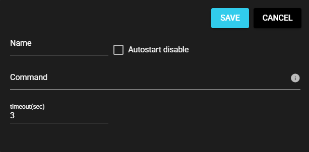
4.9.1.2 Settings#
The Shell Command settings are as follows:
| Item | Description |
|---|---|
| Name | Enter a name for the component. Note: Must be different from any other component name. |
| Autostart disable | Set to ON to disable the component’s Autostart. |
| Command | Executed shell command Note: 1 Use variables to apply the corresponding information. Note: 2 How to specify the command differs depending on the OS. Linux $HIVE_COMPONENT: Source component name of data $HIVE_DATANAME: Data name $HIVE_DATATYPE: Data type $HIVE_DATAVALUE: Value $HIVE_TIMESTAMP: Data timestamp $HIVE_DATAARRAYSIZE: Data array size Windows %HIVE_COMPONENT%: Source component name of data %HIVE_DATANAME%: Data name %HIVE_DATATYPE%: Data type %HIVE_DATAVALUE%: Value %HIVE_TIMESTAMP%: Data timestamp %HIVE_DATAARRAYSIZE%: Data array size |
| Timeout(sec) | Enter the timeout duration for command execution. |
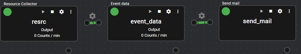
4.9.2 Send Mail#
This component sends e-mails using the collected data.
When the component receives data from the input port, it sends an e-mail with the given information to the specified address.
4.9.2.1 Basic Information#
The basic information of Send mail is as follows:
| Item | Description |
|---|---|
| Base name | Send email |
| Description | Sends an e-mail with the specified content and address, triggered by data input. |
| Consumption points | 2 |
| Port | Input: 1 Receives data from other components. Output: 0 System: 1 Outputs the component’s operating status and error information. For details on the output error information, see List of Error Codes. |
| Other | You can test connection with the e-mail server. For more information, see Test Connection. |
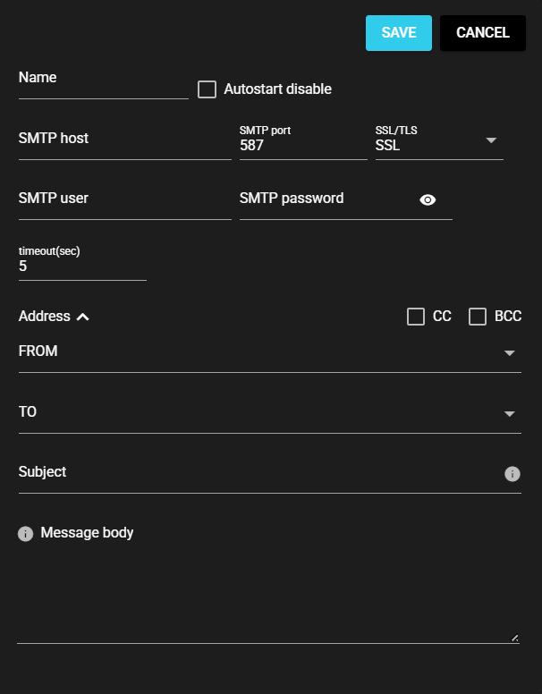
4.9.2.2 Settings#
The Send mail settings are as follows:
| Item | Description |
|---|---|
| Name | Enter a name for the component. Note: Must be different from any other component name. |
| Autostart disable | Set to ON to disable the component’s Autostart. |
| SMTP host | Host name or IP address of the SMTP server for sending e-mails. |
| SMTP port | Port for SMTP server used for sending e-mails |
| SSL/TLS | e-mail encryption protocol |
| SMTP user name | User name required for SMTP authentication for sending e-mails |
| SMTP password | Password required for SMTP authentication for sending e-mails |
| Timeout(sec) | Maximum time spent on sending an e-mail |
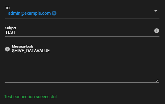
| FROM | e-mail address of the sender of the e-mail sent |
| TO | e-mail address of the recipient of the e-mail sent |
| CC | e-mail address of the recipient (CC) of the e-mail sent |
| BCC | e-mail address of the recipient (BCC) of the e-mail sent |
| Subject | Subject of the e-mail sent Note: Use variables to apply the corresponding information. For more information, see Available Variables for Send mail. |
| Message body | Message body of the e-mail sent Note: Use variables to apply the corresponding information. For more information, see Available Variables for Send mail. |
4.9.2.2.1 Available Variables for Send mail#
| Variable name | Description | Example of converted string |
|---|---|---|
| $HIVE_COMPONENT | Source component name of data | plc-collector |
| $HIVE_DATANAME | Data name | D110 |
| $HIVE_DATATYPE | Data type | double |
| $HIVE_DATAVALUE | Value | 123.45 |
| $HIVE_DATAARRAYSIZE | Data array size | 0 |
| $HIVE_TIMESTAMP | Data timestamp | 1733356200123456789 |
| $HIVE_TS | Data timestamp(in seconds) | 1733356200 |
| $HIVE_TS_MSEC | Data timestamp(in milliseconds) | 1733356200123 |
| $HIVE_TS_USEC | Data timestamp(in microseconds) | 1733356200123456 |
| $HIVE_TS_NSEC | Data timestamp(in nanoseconds) | 1733356200123456789 |
| $HIVE_TS_DATE_LOCAL | Date of data timestamp(Local Time Zone) | 2024-12-05 |
| $HIVE_TS_DATE_UTC | Date of data timestamp(UTC) | 2024-12-04 |
| $HIVE_TS_TIME_LOCAL | Time of data timestamp(Local Time Zone) | 08:50:00 |
| $HIVE_TS_TIME_UTC | Time of data timestamp(UTC) | 23:50:00 |
| $HIVE_TS_DATETIME_LOCAL | Date and time of data timestamp(Local Time Zone) | 2024-12-05T08:50:00 |
| $HIVE_TS_DATETIME_UTC | Date and time of data timestamp(UTC) | 2024-12-04T23:50:00 |
| $HIVE_TS_TZ_DIFF | Local time zone difference | +0900 |
Description of Variable Name
- The variable name HIVE_ can also be written as SYNAPSE_.
- Three formats can be used for describing variables: $HIVE_COMPONENT, ${HIVE_COMPONENT}, and %HIVE_COMPONENT%.
4.9.2.3 Test Connection#
You can test connection with the specified destination by following the steps below:
-
Open the settings screen for the registered Send mail.
-
Press [Test].

-
Test connection is attempted with the specified destination, and the result is displayed at the bottom of the settings screen.
4.9.3 PLC Writing#
This component writes values to PLC registers.
When it receives trigger data from the input port, a value can be written to the specified register of the PLC.
Fix values, trigger data values, and data values of other components can be specified as values to be written.
4.9.3.1 Basic Information#
The basic information of PLC Writing is as follows:
| Item | Description |
|---|---|
| Base name | PLC Writing |
| Description | Writes a value to the specified register of the PLC, triggered by data input. |
| Consumption points | 2 |
| Port | Input: 1 Receives data from other components. Output: 0 System: 1 Outputs the component’s operating status and error information. For details on the output error information, see List of Error Codes. |
| Other | You can test connection with PLCs. For more information, see Test Connection. |
4.9.3.2 Setting Method#
You can set up PLC Writing by following the steps below:
-
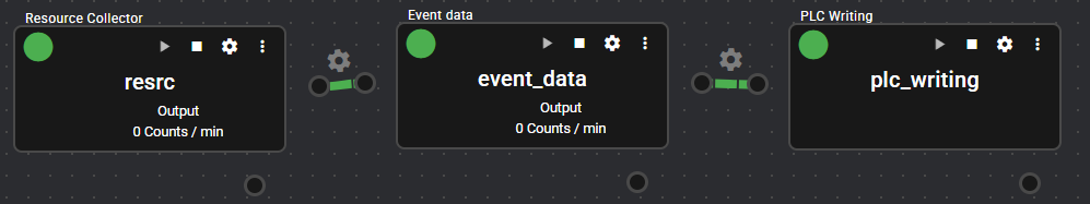
Add a component that has an output port. For instructions on how to add components, see Adding Components.
-
Start the added component and output data. For instructions on how to start components, see Starting/Stopping Components.
-
Add PLC Writing. For instructions on how to add components, see Adding Components.
-
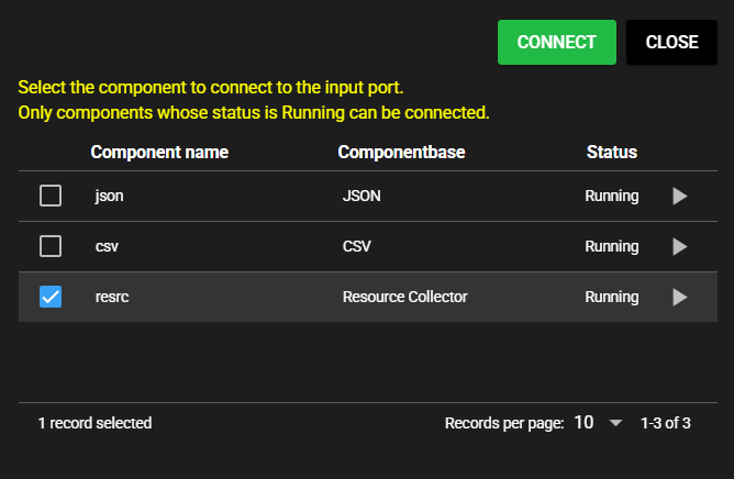
Select the added component as the component to connect to the input port.
-
Enter the following component information.
-
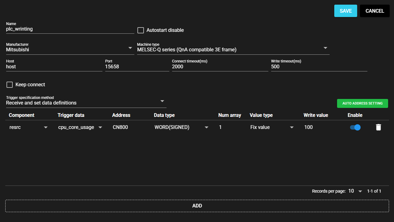
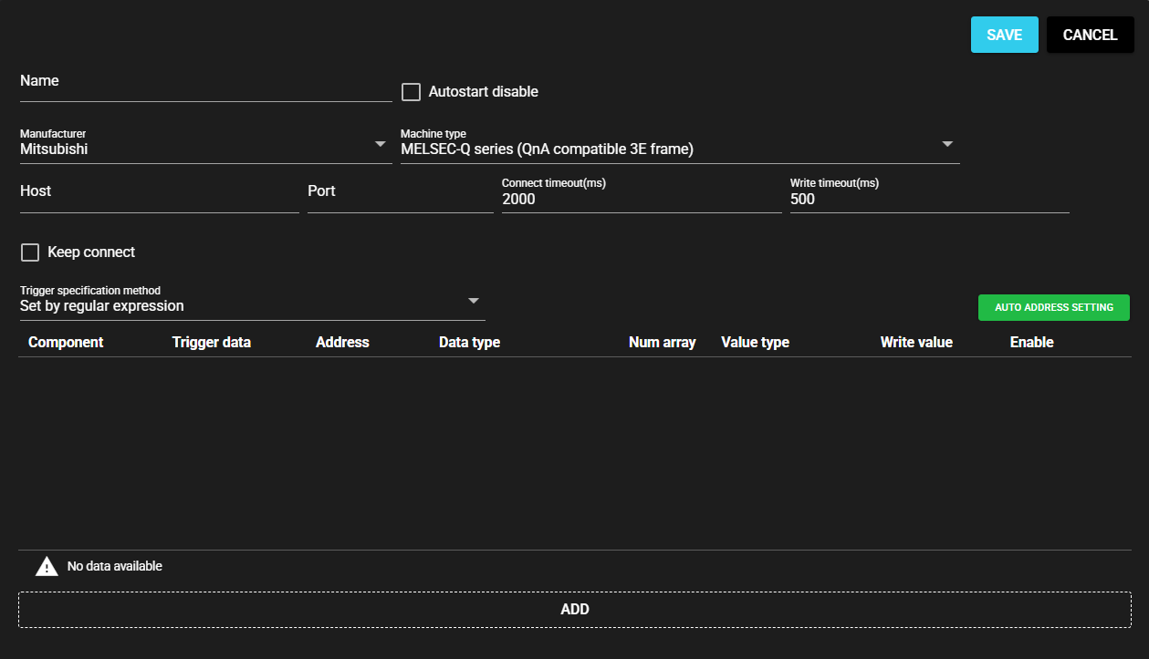
TCP/IP Connection
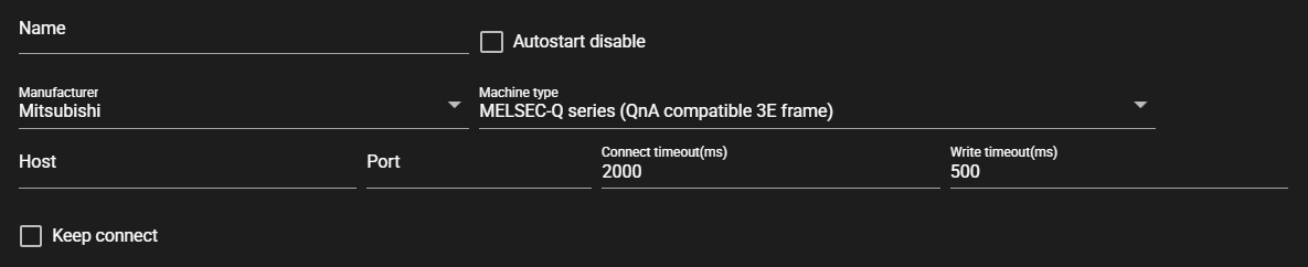
Item Description Name Enter a name for the component.
Note: Must be different from any other component name.Autostart disable Set to ON to disable the component’s Autostart. Manufacturer Select the manufacturer of the connecting PLC.
Note: You can select from the following manufacturers:
- Mitsubishi
- Jtekt
- Omron
- Keyence
- PanasonicMachine type Select the machine type of the connecting PLC.
Note: Machine types that can be selected depend on the manufacturer.Host Host or IP address of the connecting PLC Port Port for connecting PLC Connect timeout (ms) Maximum time spent on connecting to a PLC Write timeout (ms) Maximum time spent on writing a value Keep connect Do not disconnect the connection to the PLC each time a query is made. -
Serial Connection
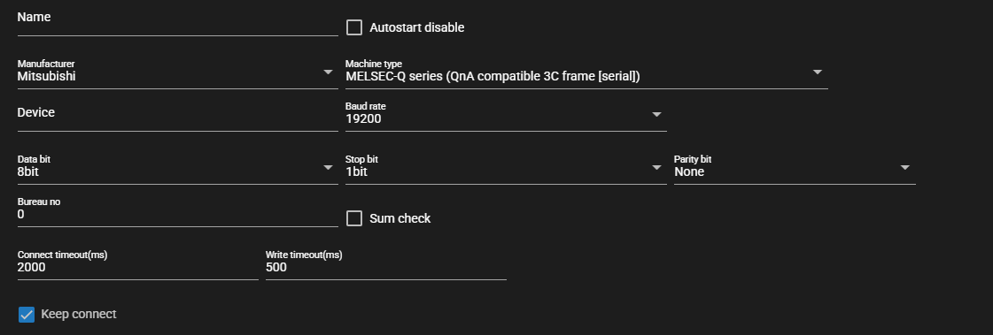
Item Description Device Enter the serial communication device to use Baud rate Select the baud rate for serial communication Data bit Select the data bits for serial communication Stop bit Select the stop bits for serial communication Parity bit Select the parity bits for serial communication Bureau no Enter the bureau number for Mitsubishi 3C frame Sum check Set to ON to perform sum check for Mitsubishi 3C frame
-
-
Select a trigger specification method from the following:
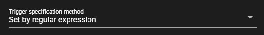
Item Description Set After Receiving Data Definitions From the list of data received by the input port, select the data that will trigger writing. Set by regular expression A regular expression is input, and among data received by the input port, the matching data is the trigger for writing. -
Enter the following items for the data to be set:

Item Description (If the Setting Option is “Set by regular expression”) Component From the data received by the input port, the regular expression that represents the component name for the data to be the trigger for writing Trigger data From the data received by the input port, the regular expression that represents the data name for the data to be the trigger for writing (If the Setting Option is “Set After Receiving Data Definitions”) Component From the data received by the input port, select the component to be the trigger for writing. Trigger data From the data received by the input port, select the data to be the trigger for writing. (Common) Address Address of register to which the value is written Program Program number of register to which the value is written
Note: Available only when the manufacturer is Jtekt.Data type Data type of register to which the value is written Num array Range to which value is written from among the consecutive registers starting from the input address Value type - Fix value: Enter a fixed value as the Write value.
- Component: Select the data received by the input port as the Write value.
- Event: Trigger data value is written.Write value Enter a value of the selected Value type.
Note: Cannot be entered when the Value type is Event.Enable To write or not Examples of Regular Expression Input
Here are examples of regular expression input:
- Matches only “data1”: data1
- Matches only data with “abc” in name: .*abc.*
- Matches only data whose name starts with “abc”: abc.*
- Matches only data whose name ends with “abc”: .*abc
-
Press [Save].
-
Start the component. For instructions on how to start components, see Starting/Stopping Components.
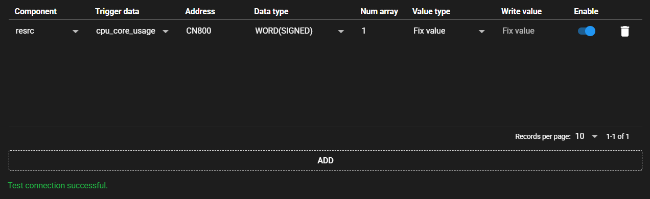
4.9.3.3 Test Connection#
You can test connection with the specified destination by following the steps below:
-
Open the settings screen for the registered PLC Writing.
-
Press [Test].
-
Test connection is attempted with the specified destination, and the result is displayed at the bottom of the settings screen.
4.9.3.4 Auto address setting#
With some PLCs, you can set addresses automatically at once by reading the file output by the ladder editing tool.
-
In the ladder editing tool, output the created ladder as a file. The output file format differs depending on the PLC manufacturer and machine type. Sample files are provided below:
-
Mitsubishi MELSEC-Q series (QnA compatible 3E frame), MELSEC-iQ-R series (QnA compatible 3E frame)
-
Omron SYSMAC CS/CJ/CP/NSJ series (FINS)
-
-
Press [Auto address setting].
-
Select the file that you output with the ladder editing tool.
-
The address is automatically set based on the file.
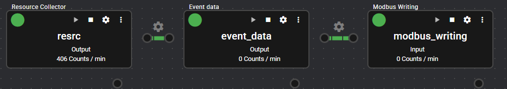
4.9.4 Modbus Writing#
This component writes a value to the specified address of a Modbus compatible device.
When trigger data is received from the input port, this component acts as the master of Modbus and writes a value to the specified register of the Modbus slave device.
Fix values, trigger data values, and data values of other components can be specified as values to be written.
4.9.4.1 Basic Information#
The basic information of Modbus Writing is as follows:
| Item | Description |
|---|---|
| Base name | Modbus Writing |
| Description | Writes a value to the specified register of the Modbus compatible device, triggered by data input. |
| Consumption points | 2 |
| Port | Input: 1 Receives data from other components. Output: 0 System: 1 Outputs the component’s operating status and error information. For details on the output error information, see List of Error Codes. |
| Other | You can test connection with Modbus compatible devices. For more information, see Test Connection. |
4.9.4.2 Setting Method#
You can set up Modbus Writing by following the steps below:
-
Add a component that has an output port. For instructions on how to add components, see Adding Components.
-
Start the added component and output data. For instructions on how to start components, see Starting/Stopping Components.
-
Add Modbus Writing. For instructions on how to add components, see Adding Components.
-
Select the added component as the component to connect to the input port.
-
Enter the following component information.
-
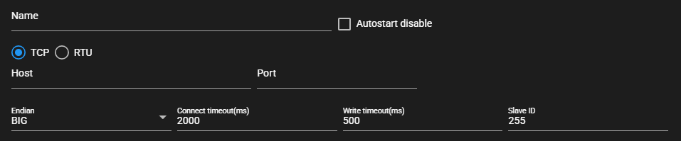
When TCP is selected as the communication method
-
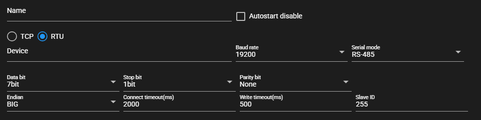
When RTU is selected as the communication method
Item Description Name Enter a name for the component.
Note: Must be different from any other component name.Autostart disable Set to ON to disable the component’s Autostart. Communication method Select TCP or RTU Host Host name or IP address of the connecting device
※Available when communication method is TCPPort Port for the connecting device
※Available when communication method is TCPDevice Serial communication device to use
※Available when communication method is RTUBaud rate Baud rate for serial communication
※Selectable when communication method is RTUSerial mode Serial communication mode
※Selectable when communication method is RTUData bit Data bits for serial communication
※Selectable when communication method is RTUStop bit Stop bits for serial communication
※Selectable when communication method is RTUParity bit Parity bits for serial communication
※Selectable when communication method is RTUEndian Byte order of the value to be written Connect timeout (ms) Maximum time spent on connecting to a device Write timeout (ms) Maximum time spent on writing a value Slave ID Slave ID of connecting device -
-
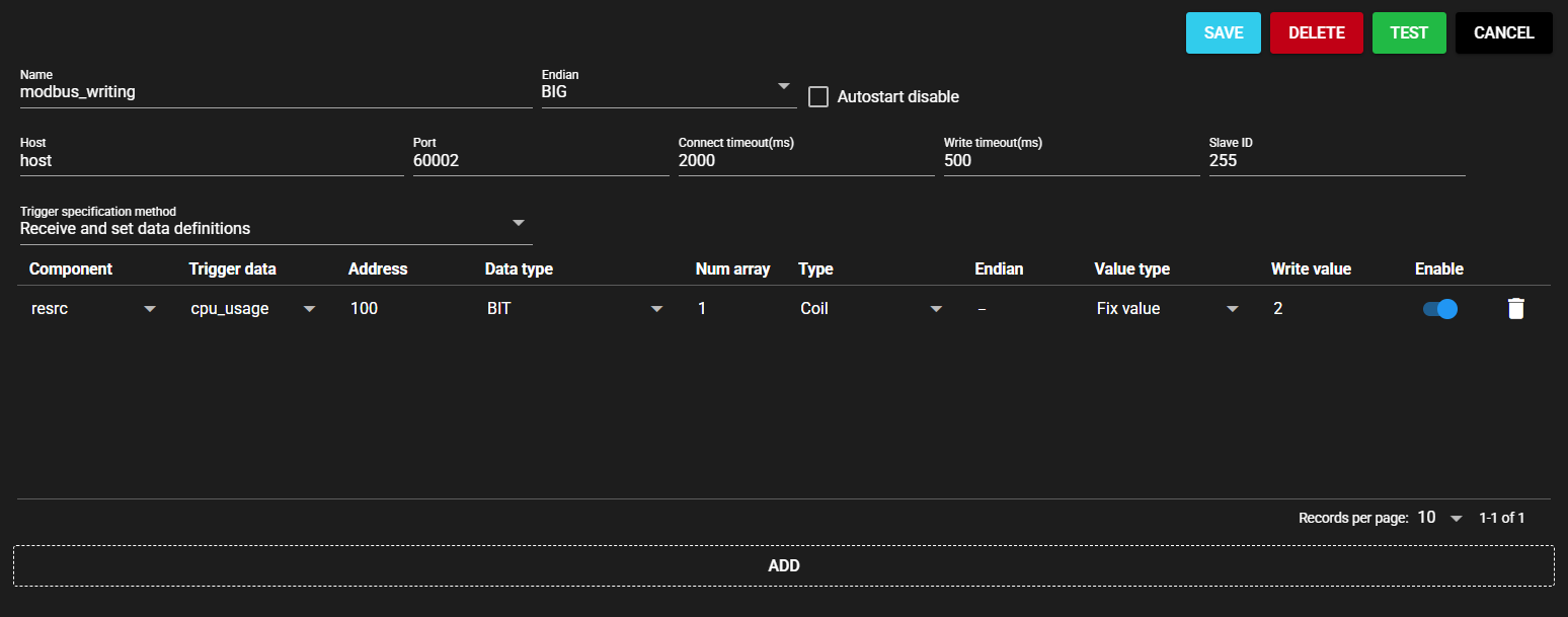
Select a trigger specification method from the following:
Item Description Set After Receiving Data Definitions From the list of data received by the input port, select the data that will trigger writing. Set by regular expression A regular expression is input, and among data received by the input port, the matching data is the trigger for writing. -
Enter the following items for the data to be set:

Item Description (If the Setting Option is “Set by regular expression”) Component From the data received by the input port, the regular expression that represents the component name for the data to be the trigger for writing Trigger data From the data received by the input port, the regular expression that represents the data name for the data to be the trigger for writing (If the Setting Option is “Set After Receiving Data Definitions”) Component From the data received by the input port, select the component to be the trigger for writing. Trigger data From the data received by the input port, select the component to be the trigger for writing. (Common) Type Type of register to which the value is written Address Address of register to which the value is written
Note: According to Modbus specifications, the address range is usually set to "1 to 65536," but when setting in SpeeDBee Synapse, it is necessary to set an address range shorter by 1, specifically, as "0 to 65535."Data type Data type of register to which the value is written Num array Range to which value is written from among the consecutive registers starting from the input address Endian Byte order of data to be written
Note: If "-," the endianness of the entire data is applied.Value type - Fix value: Enter a fixed value as the Write value.
- Component: Select the data received by the input port as the Write value.
- Event: Trigger data value is written.Write value Enter a value of the selected Value type.
Note: Cannot be entered when the Value type is Event.Enable To write or not Examples of Regular Expression Input
Here are examples of regular expression input:
- Matches only “data1”: data1
- Matches only data with “abc” in name: .*abc.*
- Matches only data whose name starts with “abc”: abc.*
- Matches only data whose name ends with “abc”: .*abc
-
Press [Save].
-
Start the component. For instructions on how to start components, see Starting/Stopping Components.
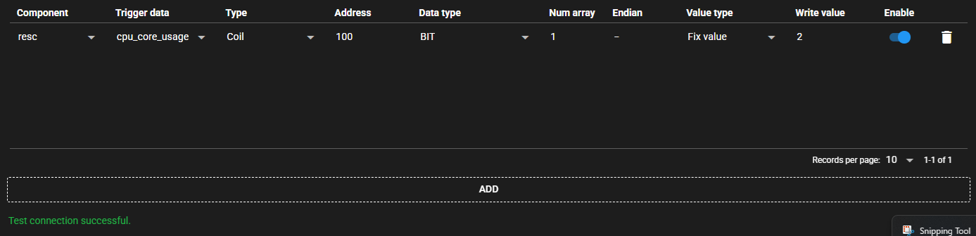
4.9.4.3 Test Connection#
You can test connection with the specified destination by following the steps below:
-
Open the settings screen for the registered Modbus Writing.
-
Press [Test].
-
Test connection is attempted with the specified destination, and the result is displayed at the bottom of the settings screen.
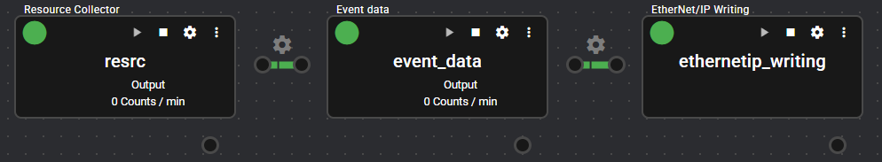
4.9.5 EtherNet/IP Writing#
This component writes a value to the specified address of an EtherNet/IP-enabled device.
When the component receives trigger data from the input port, it acts as an originator, connects to the EtherNet/IP-enabled device, and writes an arbitrary value to the specified variable.
4.9.5.1 Basic Information#
The basic information of EtherNet/IP Writing is as follows:
| Item | Description |
|---|---|
| Base name | EtherNet/IP Writing |
| Description | Writes a value to the specified variable of the EtherNet/IP-enabled device, triggered by data input. |
| Consumption points | 2 |
| Port | Input: 1 Receives data from other components. Output: 0 System: 1 Outputs the component’s operating status and error information. For details on the output error information, see List of Error Codes. |
| Other | Variables can be set automatically. For more information, see Auto variable setting. |
4.9.5.2 Setting Option#
You can set up EtherNet/IP Writing by following the steps below:
-
Add a component that has an output port. For instructions on how to add components, see Adding Components.
-
Start the added component and output data. For instructions on how to start components, see Starting/Stopping Components.
-
Add EtherNet/IP Writing. For instructions on how to add components, see Adding Components.
-
Select the added component as the component to connect to the input port.
-
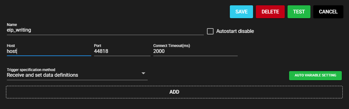
Enter the following component information.
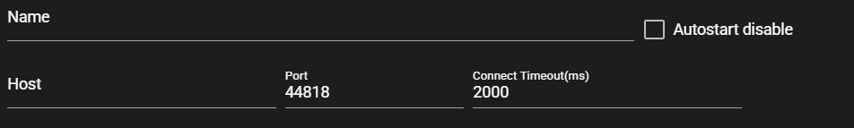
Item Description Name Enter a name for the component.
Note: Must be different from any other component name.Autostart disable Set to ON to disable the component’s Autostart. Host Enter the host name or IP address of the EtherNet/IP-enabled device. Port Enter the port for the EtherNet/IP-enabled device. Connect timeout(ms) Enter the timeout duration for connecting. -
Select a trigger specification method from the following:

Item Description Set After Receiving Data Definitions From the list of data received by the input port, select the data that will trigger writing. Set by regular expression A regular expression is input, and among data received by the input port, the matching data is the trigger for writing. -
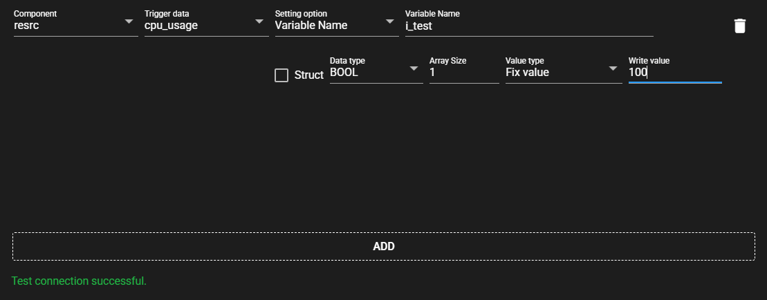
Enter the following items for the data to be set:

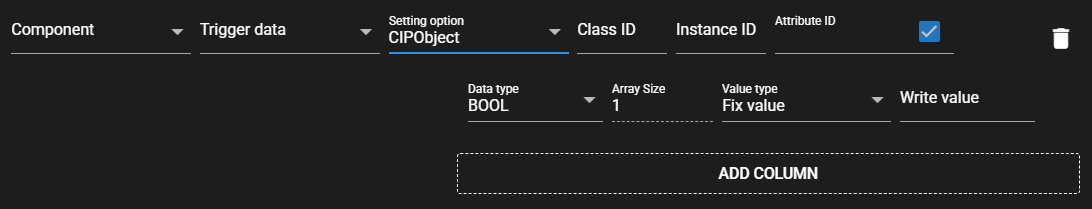
Item Description (If the Setting Option is “Set by regular expression”) Component From the data received by the input port, the regular expression that represents the component name for the data to be the trigger for writing Trigger data From the data received by the input port, the regular expression that represents the data name for the data to be the trigger for writing (If the Setting Option is “Set After Receiving Data Definitions”) Component From the data received by the input port, select the component to be the trigger for writing. Trigger data From the data received by the input port, select the component to be the trigger for writing. (Common) Setting Option Select the setting option for the data to be acquired. Variable name Enter a tag name.
Note: This item can be entered only when the Setting Option is Variable Name.Struct Set to ON to register multiple members.
Note: This item can be set only when the Setting Option is Variable Name.Class ID Enter a Class ID.
Note: This can be entered only when the Setting Option is CIPObject.Instance ID Enter an Instance ID.
Note: This can be entered only when the Setting Option is CIPObject.Attribute ID Enter an Attribute ID.
Note: This can be entered only when the Setting Option is CIPObject.Attribute settings Check when entering Attribute ID.
Note: This can be manipulated only when the Setting Option is CIPObject.Data type Data type of member Array size Array size of member
Note: This item can be manipulated only when the Setting Option is Variable Name.Value type - Fix value: Enter a fixed value as the Write value.
- Component: Select the data received by the input port as the Write value.
- Event: Trigger data value is written.Write value Enter a value of the selected Value type.
Note: Cannot be entered when the Value type is Event.Examples of Regular Expression Input
Here are examples of regular expression input:
- Matches only “data1”: data1
- Matches only data with “abc” in name: .*abc.*
- Matches only data whose name starts with “abc”: abc.*
- Matches only data whose name ends with “abc”: .*abc
-
Press [Save].

-
Start the component. For instructions on how to start components, see Starting/Stopping Components.
4.9.5.3 Test Connection#
You can test connection with the specified destination by following the steps below:
-
Open the settings screen for the registered EtherNet/IP Writing.
-
Press [Test].
-
Test connection is attempted with the specified destination, and the result is displayed at the bottom of the settings screen.
4.9.5.4 Auto variable setting#
Variables can be automatically set by converting the global variable information exported by Sysmac Studio to a text file into a specified format and reading it.
-
Convert the global variable information exported by Sysmac Studio to a text file with the following column information:
- HOST
- NAME
- DATATYPE
- ADDRESS
- COMMENT
- TAGLINK
- RW
- POU
ExampleHOST NAME DATATYPE ADDRESS COMMENT TAGLINK RW POU b_test BOOL test1 TRUE RW i_test UINT test2 TRUE RW s_test STRING(256) test3 TRUE RW -
Press [AUTO VARIABLE SETTING].
-
Select the prepared text file.
-
The variable is automatically set based on the file.
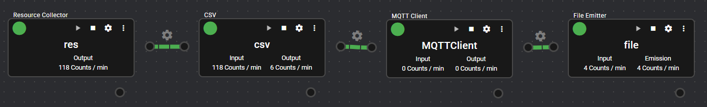
4.9.6 MQTT Client#
This component performs publish/subscribe to the same MQTT broker.
When file type data is received from the input port, its contents are published to the MQTT broker.
Subscribed data is output from the output port as file type data.
4.9.6.1 Basic Information#
The basic information of MQTT Client is as follows:
| Item | Description |
|---|---|
| Base name | MQTT Client |
| Description | A component that connects to an MQTT broker and performs bidirectional data transmission and reception. When data is received from the input port, the data is published with the specified topic name. Also, it subscribes to the specified topic name and outputs the received data from the output port. |
| Consumption points | 2 |
| Port | Input: 1 Receives data from other components. Output: 1 Outputs subscribed data. System: 1 Outputs the component's operating status and error information. For details on the output error information, see List of Error Codes. |
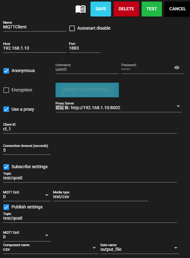
4.9.6.2 Settings#
The MQTT Client settings are as follows:
| Item | Description |
|---|---|
| Name | Enter a name for the component. Note: Must be different from any other component name. |
| Autostart disable | Set to ON to disable the component's Autostart. |
| Host | Host name or IP address of the MQTT broker |
| Port | Port number of the MQTT broker |
| Anonymous | Set to ON when not performing user authentication |
| Username | Enter authentication user name Note: Can only be entered when Anonymous access is disabled. |
| Password | Enter authentication password Note: Can only be entered when Anonymous access is disabled. |
| Encryption | Set to ON to enable encryption. |
| CA Certificate | Upload the CA Certificate to be used for encrypted communication. If not specified, CA Certificates installed on the sytem will be used. Note: You can only upload it when encryption is enabled. |
| Use a proxy | Set to ON to communicate with the MQTT broker via a proxy server |
| Proxy server | Select proxy server Note: The server to be used must be set in advance in Proxy settings. |
| Client ID | MQTT Client ID Note: May need to be specified depending on the destination specifications. Note: When multiple components connect to the same MQTT broker, ensure that Client IDs do not overlap. Communication will not work properly. |
| Connection timeout(sec) | Enter the timeout seconds when connecting to the MQTT broker |
| Subscribe settings | Set to ON to perform subscription. |
| Topic | Enter the topic to collect |
| MQTT QoS | Select MQTT Quality of Service |
| Media type | Specify the media type of the output file. |
| Publish settings | Set to ON to perform publishing. |
| Topic | Enter the topic to publish |
| MQTT QoS | Select MQTT Quality of Service |
| Component name | Specify the name of the component to collect from the data received by the input port. |
| Data name | Specify the name of the data to collect from the data received by the input port. |
4.9.6.3 Test Connection#
You can test connection with the specified destination by following the steps below:
-
Open the settings screen for the registered MQTT Client.
-
Press [Test].
-
Test connection is attempted with the specified destination, and the result is displayed at the bottom of the settings screen.